Unbelievably Sleek Fighter Cold War Combat Aircraft: Bud Nelson’s Light Fighter Concepts

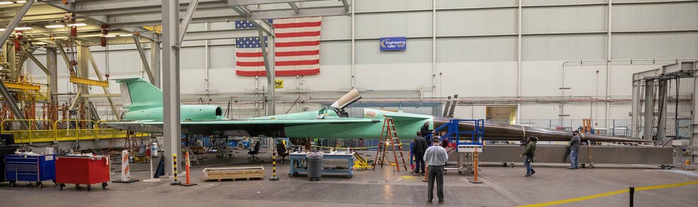
A series of sleek exotic fighter aircraft concepts were explored between 1970 and 1982 in the US. With the fabulous good looks of a fictional spaceship, these Cold War studies were extremely lightweight and often revolutionary in shape and concept. Jim Smith delves into the fascinating story of Bud Nelson’s light fight concepts.

This article stems from a detailed paper called ‘The Third Pass of the Fifth Generation‘. Yes, the title is enigmatic, but it’s possible something has been lost in translation.

The article was published in April 2020 by Kazakhstan Engineering and describes in some detail projects and concepts for very light fighters developed by American aerospace engineer Bud Nelson for first Boeing, and latterly Northrop. These projects spanned a period from 1970 to 1982, and to place these lightweight concepts in context, the Table below shows some first flight dates for other fighters in this period.

First flight Aircraft
1970MiG-27, Grumman F-14 Tomcat
1972MD F-15 Eagle
1974Northrop YF-17, GD YF-16 and Panavia Tornado
1975MiG-31
1977MiG-29, Su-27
1978MD F/A-18, Mirage 2000
1980GD F-16/79
1982GD F-16XL, F-20 Tigershark

Militarily significant world events in this period included the closing stages of the Vietnam War, and the Yom Kippur between Israel, Egypt and Syria (1973); the invasion of Afghanistan by the Soviet Union (1979); the start of the Iran-Iraq War (1980); and the Falklands conflict (1982).
A summary of the projects
• Boeing 908-909


This was Boeing’s entry to the Lightweight Fighter competition, and lost out to General Dynamics and Northrop, who received contracts to develop the YF-16 and YF-17 respectively. The general configuration of this aircraft was similar to a YF-16, single-engined, with an under-fuselage intake and single fin. However, the wing appears to be a simple swept wing, without the leading edge strake featured on the YF-16 and YF-17. In addition, the nose of the aircraft was very slender, and would not have provided sufficient space for an Airborne Intercept (AI) radar.


Having missed out on the LWF competition, Boeing was looking to establish a role for the Boeing 747 as an Airborne Aircraft Carrier (AAC), and tasked Bud Nelson designed a series of micro-fighter to come up with a fighter for this. As this would inevitably have to be small, Nelson designed a series of Micro-fighter concepts to meet the desires of the ‘Fighter Mafia’, who had advocated for the LWF program, seeking light weight and extreme manoeuvrability. The first of these was the Boeing 908-625, and later concepts were variations of the Boeing 985.

Boeing 908-625


Microfighter, for operation from flying aircraft carriers. This was a single-engined tailless aircraft, with a wing that bore a passing resemblance to that of the BAC Lightning, and a take-off weight of just 3.7 tonnes. Fins were mounted on the wingtips for directional stability and control, and the engine was fitted with a rectangular rear vectoring nozzle for pitch control. The armament was two cannon on the upper shoulders of the fuselage, and the aircraft was stressed for manoeuvres up to 8.5g.


Boeing 985-121
Designed with a similar intent to the 908-625, this featured a change in armament to carry two tip mounted guided weapons. Otherwise, the wing was changed to a lower aspect ratio, with a planform bearing a resemblance to that of the Douglas Skyray. The tip fins and vectoring rear nozzle were retained.
• Boeing 985-213


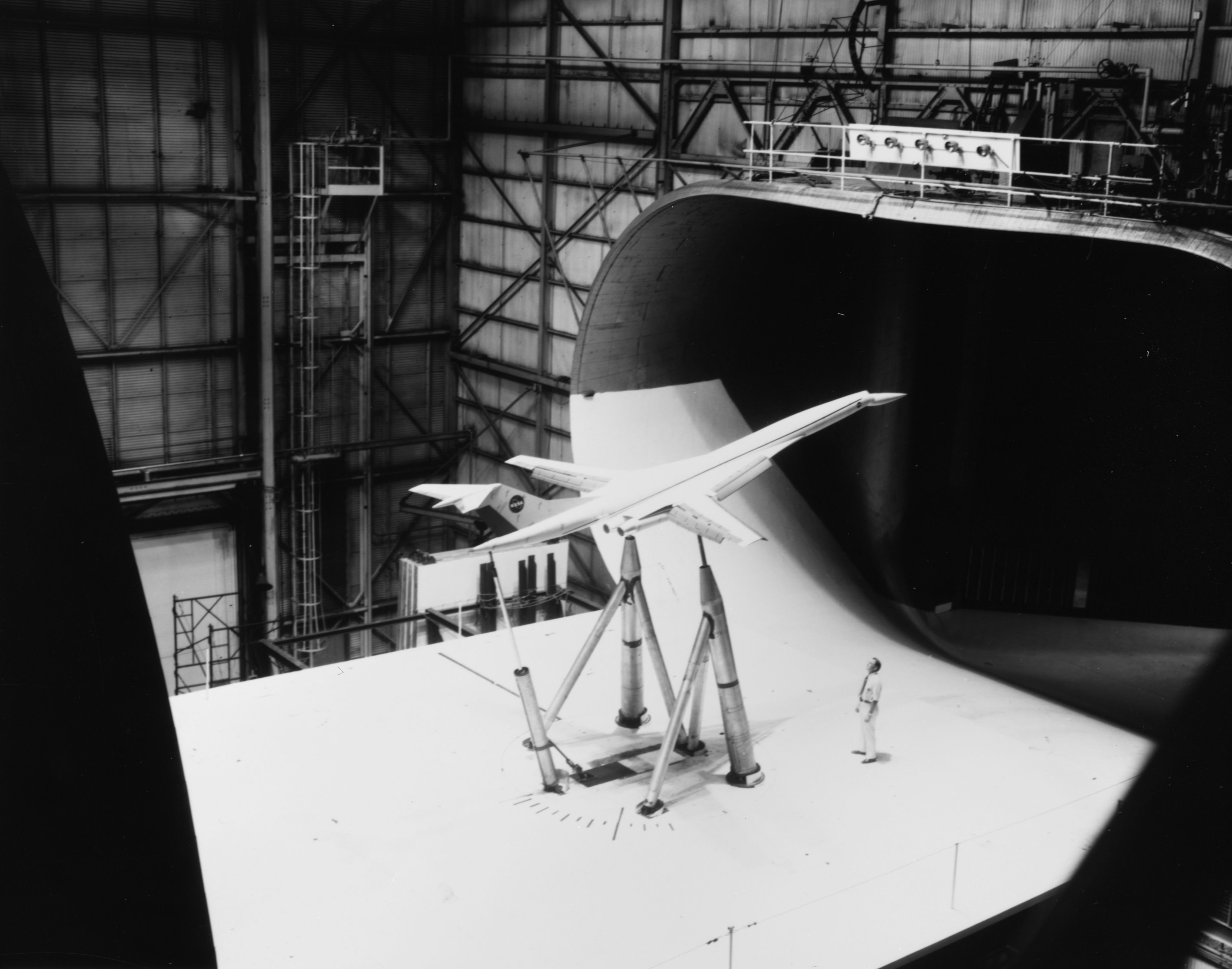
The 985-213 was developed as larger, higher performance version of 985-121. The wing planform was dramatically different. Very highly-swept and highly-tapered, this was an arrow wing with conical camber, and was derived from concepts examined in the Supersonic Civil Air Transport (SCAT) program. The wing tips could fold down to improve subsonic lift, and the tail fins were mounted at about about 80% span rather than at the wingtips.
The concept was armed with 2 missiles, carried on the upper fuselage shoulders in a retractable installation, together with a 3-barrel 20mm cannon for ground attack. The concept appears to have a very small radar, and a tricycle undercarriage to allow recovery to an airfield if necessary, the primary operating base remaining the Boeing 747 AAC.
The performance claimed was Mmax 2.2, with supercruise possible to M 1.6. A combination of reduced stability, coupled with light weight and thrust vectoring was expected to allow the aircraft to manoeuvre at up to 8g at Mach 0.8.


Swing-wing variant
The airborne aircraft carrier concept was eventually abandoned, but efforts continued, looking at similar configurations. This now would need to operate from an airfield, and need improved take-off and landing performance, and increased fuel. A twin-engine configuration was examined, with a wing like the 908-909, but variable sweep. This included un-sweeping the wing tips to keep the tip fins aligned. Unsurprisingly, this variant was considered to be too big, too complex, and to have too high a weight penalty.


Light Experimental Supercruiser (LES)


By 1976, the Air Force had concluded that the aircraft was too operationally inflexible, so the concept was reworked to introduce a canard. The wing-tip fins and the vectoring nozzle were retained, and two missiles were to be carried under fuselage. The intent at this stage was for the concept to support to heavy fighters as a front-line interceptor.
The concept continued to evolve, with the design reverting to the highly-swept and tapered arrow wing used on the 985-213, but with a simpler profile. In response to the concerns about armament, provision was made for underwing stores carriage, and vertical variable ramp inlet used. These measured impacted on both weight and drag, and supercruise capability was now limited to M1.3 and max speed Mach 1.8.
Take-off weight was increased to 7.5 tons, and, for comparison, the YF-16A had an empty weight of 6.4 tonnes, and a loaded weight of 9.7 tonnes.


Northrop
In 1978 Nelson and his team left Boeing and moved to Northrop. At this time, Northrop had the F-5E/F in production, and was working with McDonnell-Douglas on the development of the F-18. Nelson’s initial task at Northrop was to work on the F-18L variant of the Naval F/A-18A, intended for export and for land-based operations. Then in 1980, a lighter and cheaper aircraft to complement what was then the ATF was sought, as the Mission Adaptive Fighter.


•
Nelson’s concept for this program had the same basic arrow-wing, tip fins plus rectangular thrust vectoring nozzle as the earlier Boeing concepts, but buried and screened intakes in the leading edge, and inward canted fins to reduce radar signature.
Weapons were to be carried in an internal launcher system, which was deployed when needed, but was otherwise within the fuselage to reduce signature and drag. A mix of weapons were proposed including up to 4 air to air missiles, or 40 unguided CRV 7 rockets, or a minigun plus a reduced mixed missile load.
The aircraft was unstable, with a digital flight control system. Avionics for this and other systems were modularised and easily swapped out to expedite repairs and increase aircraft availability. The take-off weight was about 7.7 tonnes, and supercruise capability was sacrificed in the pursuit of reduced signature and high manoeuvrability, the structure being rated for 10g manoeuvres.


• Northrop N-356


This was an export version of the N-353, with a simplified wing, F-18-like intakes, and external weapons carriage under the fuselage. The wing-tip fins were replaced by a single central fin, allowing the carriage of tip-mounted AAMs.

Commonality with the F-18L was sought where possible, and all of the changes in design both added weight and decreased manoeuvre performance. The manoeuvre capability was 7.5g, but up to 6 AAM could be carried.
The USAF took a policy decision in the same period to focus on low observables as the way ahead, and that was that.

So what went wrong?


Some of the aircraft in this saga of wasted effort looked absolutely uber-cool, in a Gerry Anderson kind of way, but ultimately, in my view, the whole program was utterly misconceived and, even if supported by the Air Force, would not have produced an aircraft competitive with the F-16.
This sounds harsh, but the tides of history and technology development at the time were running against the lightly-armed but highly-manoeuvrable concepts that were being considered.
This saga provoked me into thinking in general terms about Light Fighters and their history, and why Light Fighter proposals appeared, and continued to appear seemingly throughout the long history of air combat.

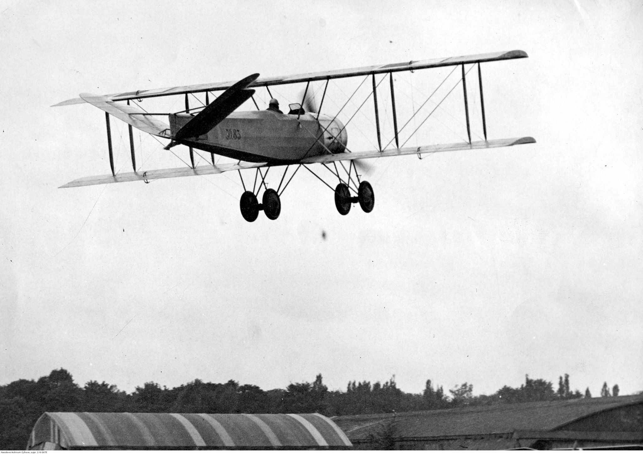
It seems to me that there was a long period, from the beginnings of air combat, right through to about the end of the Korean War, or just possibly the start of the Vietnam War, where there was genuine competition between the Light and the Heavy fighters.


In this period, air combat was overwhelmingly visual air combat, aimed at getting one aircraft’s guns to bear on the other. In these circumstances, lighter aircraft could often out-turn heavier ones, making themselves difficult targets, and obtaining success in a turning fight. Heavier aircraft were generally faster and better armed, and they could obtain success by using ‘slashing’ tactics and avoiding turning combat, and, perhaps taking the combat into the vertical plane if they had sufficient speed and climb-rate advantage.
I wonder whether the proponents of the ‘Fighter Mafia’ were in effect still fighting these conflicts.
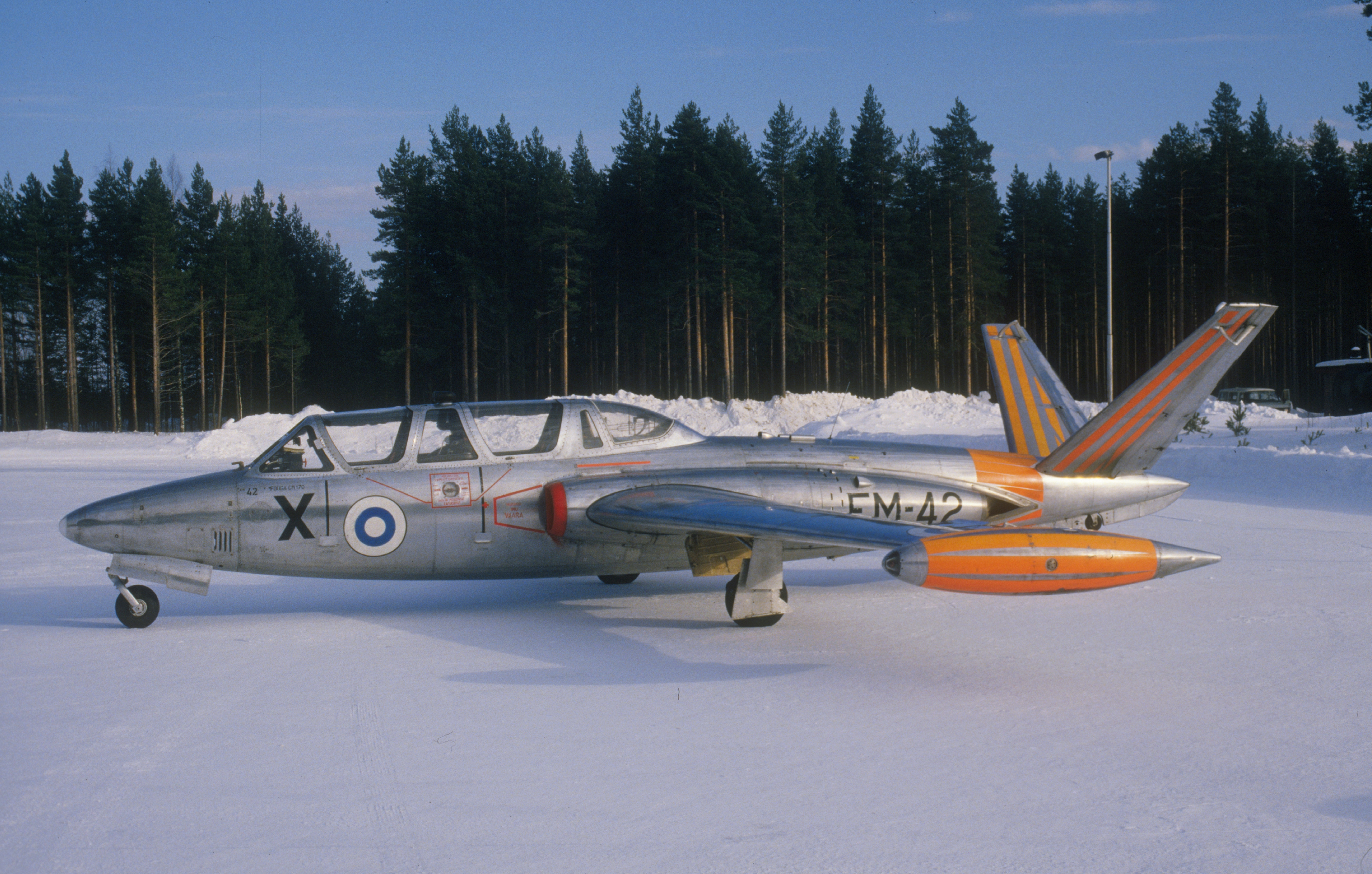
After this period, lightweight fighters were still being constructed, but, as set out in my historical piece, were perhaps of greater importance for smaller air arms, or for the Client States of the major powers. Indeed, the Northrop F-5 Freedom Fighter would be an excellent example of such an aircraft.
For the major powers, air combat had been transformed by the development of effective infra-red, and later radar-guided, air-to-air missiles (AAM). These missiles resulted in a technology landscape favouring the heavy fighter, with a radar, possibly two crew, and a mix of IR and radar-guided AAM. Progressive development of radars, missiles, and missile seekers has resulted in a situation where Beyond Visual Range (BVR) air combat is preferred. Short-range manoeuvring air combat is something to be avoided if possible, as the expected result is, all too often, a mutual kill.


As technology is continuing to evolve, lighter-weight fighters are making a come-back, as aircraft like the Gripen and Tejas are demonstrating that highly integrated systems with long-range missiles and highly effective sensors can now be packaged into a single-engined and single-seat airframe. Late model F-16C/D also have BVR capability, but are more often used as multi-role tactical strike aircraft than as BVR Air Defence assets.


The Boeing airborne aircraft carrier concept was doomed, probably from the outset. Against what has proven to be a very successful and very versatile F-16 aircraft, exported around the world, and built in the thousands, the most fully-developed concept, the 985-213, comes up short.
A package consisting of the 747 carrier and four 985-213 offers a capability of just eight AAM, but requires five aircraft, and at least seven aircrew to achieve this. In addition, the vulnerability of the carrier aircraft is such that it is questionable what penetration of enemy airspace could have been achieved.
Efforts to develop a viable land-based version of the aircraft ran into the problem that additional fuel would be required to achieve a useful combat capability, and the most fully developed land-based variant, the Northrop N-353 would end up competing against the same company’s lower risk, but ultimately still unsuccessful F-20 Tigershark.
A detailed article on the F-20 and the Israeli Lavi can be found here.
While there was some interest in the N-356 in the export market, I’d suggest the aircraft would not have been competitive with the F-16, which was being made available for export, at least to some Nations, in the same timescale.
All in all, a sorry saga, and a demonstration that even if it looks uber-cool, it’s not necessarily the right answer. It might, indeed, be the answer to the wrong problem.

10 Most Important Aircraft in Irish History

The fascinating aviation history of Ireland is seldom covered, so in an attempt to rectify this we asked Michael Carley to pick the 10 most important aircraft in Irish history. Though the Seafire and Lysander were operated by the Irish armed forces, they don’t make the cut for historical importance. The following 10 aircraft paint a fascinating picture of Ireland’s unique aeronautical history.

(The lovely Seafire image above is by Edward Ward for Hush-Kit and is available on a variety of high-quality items here.)

PILATUS PC-9M
The current top end combat aircraft of Ireland is the Swiss Pilatus PC-9M.

10. Martinsyde Type A

martinsydeairlanda1921-1024x363

Everything in Ireland happens twice: once when we claim independence, once when we get it. The first Dáil Éireann (national assembly), containing a large contingent of men with a price on their heads, met three years before Ireland was granted formal independence. In between, the Irish government negotiated with the United Kingdom, leading to the notorious Treaty, which was signed just over a century ago. When the Irish delegation went to London to make the deal, they had no idea how things might turn out and felt the need of a getaway vehicle, in particular for Michael Collins, a man worth ten grand, dead or alive.

Two former RAF men, William McSweeney and Charles Russell, now serving in the IRA, were sent to buy an aircraft and have it ready for a quick exit should talks fail. Laundering the money through the Irish Self-Determination League of Great Britain, the Dáil paid three thousand for a Martinsyde Type A, and the Irish Air Corps had its first aircraft, christened ‘The Big Fella’, after Collins. The Martinsyde cabin was modified to carry five people, and the aircraft was stashed at Brooklands, where a Captain Clarke was slipped twenty five quid to make sure it was ready at short notice. If talks had collapsed and Collins had to take a runner, Russell have flown him from Brooklands to Leopardstown racecourse in Dublin, routing via Bristol and Wexford.

In the event, the talks led to the Treaty, which was endorsed by Dáil Éireann (another, ongoing, story) and the escape plan was dropped. The Martinsyde was taken over by the Air Corps at independence, though it was of little use in the Civil War and was mainly used for VIP transport. It was scrapped in 1937 after a decade out of service, being used to train ground crew.

9. Bristol F.2 Fighter

Bristol F.2 Fighter - Wikiwand
There are not many photographs of Irish F.2, so instead here is a Bristol F.2B Fighter of No. 1 Squadron, Australian Flying Corps flown by Ross Smith in Palestine, February 1918.

The Bristol F.2 was the first aircraft the Irish Army National Air Service acquired without having to approach a dodgy aeroplane dealer. By the end of 1922, the air service had ten aircraft, six F.2s and four Martinsyde Type As. The F.2 was a reasonably capable aircraft for the period and started the practice of Ireland not being as far behind the rest of the world as some people assume. Ten years later, the air corps was flying Gloster Gladiators and by the end of the Second World War, it was replacing Hurricanes with Seafires. It had also introduced the coolest roundel on the planet.

Shortly after the Civil War, the National Air Service became the Army Air Corps with its headquarters at Baldonnel, south of Dublin, near where I grew up. Baldonnel Aerodrome was later named after Sir Roger Casement. Britain had knighted him for his work exposing abuses in the rubber-tapping industry, and hanged him for trying to bring German guns into Ireland for the 1916 Rising. That would probably make the headquarters of the Irish Air Corps the only military airfield in the world named after a gay icon.

8. de Havilland DH.84 Iolar

De Havilland DH84 Dragon EI-ABI

Frank Zappa allegedly reckoned you’re not a real country unless you have a beer and an airline. Ireland has a beer older than the state, which causes all sorts of trademark issues, but it didn’t get an airline until April 1936 when Aer Lingus (in English “air fleet”, or in Russian, aeroflot) was founded. Its first aircraft was a de Havilland DH.84, called Iolar (“Eagle”). The first scheduled service was from Baldonnel (now Casement Aerodrome) to Bristol (Whitchurch). A second aircraft, a DH.86 Éire was used to extend the Bristol service to Croydon, and the DH.84 began the first Dublin–Liverpool service. According to Wikipedia, the Dublin–London route is the second busiest international route in the world, after Hong Kong–Taipei. That’s a lot of miserable people being flown by Ryanair.

Iolar is no more, but Aer Lingus did restore another DH.84 as a replica.

OX-5

7. Customised Curtiss-Robin OX-5

Alcock and Brown made the first flight between North America and Ireland, but they crashed in a field in Galway. Douglas Wrong Way Corrigan flew from Brooklyn to Dublin and landed at the Irish Air Corps’ Baldonnel Aerodrome, in 1938. Corrigan was an aircraft mechanic who had worked on Lindbergh’s Spirit of Saint Louis and wanted to repeat the trip, selecting Ireland as his destination. After getting a transport pilot’s licence, bought a used Curtiss-Robin OX-5 and took it home to California. He upgraded the aircraft with extra fuel capacity and a new engine made of two old Wright Whirlwinds. This was enough to get him permission for cross-country flights, but permission for a transatlantic attempt was denied. By 1937, he had improved the aircraft so much that he was denied permission to fly it all. Flying on an experimental aircraft permit, he travelled from California to New York, as a test of the aircraft’s range. That flight took 27 hours, the last few of which were marred by fumes in the cockpit from a fuel leak.

Greatest trolling in newspaper history

At Floyd Bennett field, Corrigan filed a flight plan for return to California, took off, and headed east instead of west. After ten hours, he made a hole in the floor to drain the fuel leaking into the cockpit. After twenty six hours, he realised he had been going the wrong way. Two hours after that he landed in Baldonnel. He was barred from flying for fourteen days. On the day his suspension expired, he arrived by steamer in New York by steamer, with his aeroplane.

6. Boeing 314

Foynes Flying Boat Museum - All You Need to Know BEFORE You Go

Before there was Shannon Airport, there was Foynes Flying Boat Station. On the Shannon estuary, it was the point of entry for flying boats from Newfoundland, Montreal, Poole, and Lisbon. Pan Am’s Yankee Clipper was the first Boeing 314 assigned to the Atlantic routes and made its proving flight to Foynes in April 1939. For a few years afterwards, Foynes was one of the biggest civilian airports in Europe, mainly because it was one of the few in a neutral country. The 314 was the civilized way to cross the Atlantic, if you had the cash. Dinner was served on linen, wine came in crystal, and when you woke up in the morning, your freshly polished shoes were next to your bed. It also had a celestial observation turret. Every home should have one.

Foynes was closed in 1946 and its place in transatlantic aviation was taken by Shannon Airport on the other side of the estuary. Shannon’s first transatlantic flight took place in 1945 and in 1947 it became the world’s first duty-free airport. Foynes claims the credit for inventing the Irish coffee, as a way of warming up flying boat passengers who needed reviving.

In 1989 I spent a long time at Shannon because a bunch of Cubans had defected in Gander.

5. Short Sunderland

Short Sunderland - Wikipedia

The Short Sunderland, ‘Flying Porcupine’ to the enemy, was the first of their own aircraft which Short Brothers built at their Belfast plant. They had set up a plant there, to supplement production in Rochester, and started off by producing Bristol Bombays and Handley-Page Herefords. The Sunderland is probably the first production aircraft you could meaningfully call ‘Irish’. It flew in the Battle of Atlantic, the Korean War, and the Berlin Airlift. It was heavily armed, purposeful, and looked just the way you’d hope a military flying boat would. It did anti-submarine warfare, search-and-rescue, and maritime reconnaissance.

It’s a miracle Short Brothers managed to build it. They were so badly run, the state stepped in. In 1943, “left to their own devices the management of Short Brothers had not succeeded in putting their house satisfactorily in order”, so the British government nationalised them. Then it denationalised them.

4. Fouga Magister

The Fouga was the second Magister flown by the Air Corps: one of their Miles Magisters is hanging up in the National Museum in Dublin. The National Museum also has Ireland’s other exotically-tailed fast (ish) jet, a de Havilland Vampire. The Vampire and the Magister were probably the last time Ireland flew fixed-wing aircraft that you could call “advanced”, and even then it’s a stretch. Today, the Air Corps flies modern aircraft of their type (CN-235, PC-12, EC135, AW139, PC-9) but realistically Ireland doesn’t need fast jets.

The Magister gets the nod here because it was a bit more modern, and a bit more shinier than the Vampire. It was also the last jet operated by the Air Corps, other than the Gulfstream IV and the Learjet used for VIP and medical transport. The Magister entered Irish service in 1975 and was flown until 1999 as a trainer and as the Light Strike Squadron. Four Magisters formed the corps’ display team, the Silver Swallows. In 1997, they appeared at Fairford and won the Lockheed Martin Cannestra Trophy for the Best Display by an Overseas Performer, which isn’t a bad way to close an era.

If you were on your way down the Blessington Road back into Tallaght, you would occasionally see the Silver Swallows practicing. Side on. They liked to get close to the ground.

Pre-order The Hush-Kit Book of Warplanes 3 here

If you enjoyed this free article support The Hush-Kit Book of Warplanes Vol 2 by pre-ordering your copy here. 

(link goes to volume 2 but you can find volume 1 on the same site)

Short SC.7 Skyvan wiki | TheReaderWiki

3. Short ‘Vomit Comet’

The Short Skyvan and its descendants, the 330 and the 360 are proof that you really can make a brick fly if you put an adequate wing on it. Presumably, somebody had stolen the compasses from the design office and they had to use a ruler for everything. They ended up designing an aircraft that was a very convenient shape for putting square boxes into. It was not a convenient shape for air to flow over. It was noisy and sickness-inducing. The US Air Force bought a few, calling them the C-23 Sherpa, after people who go to great heights without pressurisation.

They were also popular with skydiving clubs, presumably because being a passenger in one made throwing yourself out the door an attractive proposition.

Embraer EMB110 Bandeirante

2. Embraer EMB 110 Bandeirante

First Versions: Ryanair

A what? The EMB110 is an eighteen passenger twin turboprop designed in the 1960s. In 1985, an Irish company called Danren Enterprises started flying them from Waterford to Gatwick. Not long afterwards, the owners, Christopher Ryan, Liam Lonergan, and Tony Ryan, renamed the company.

Look, do I have to spell this out?

1. Short SC.1

SHORT SC1 - Flight Manuals

Short Brothers had their moments, it is fair to say. The SC-1 was a stubby little delta-wing affair with five engines: one pointing backwards and four pointing down. It made its first flight in April 1957, using the backward-pointing engine. In May 1958, a second SC-1 made a tethered hover, using the downward-pointing engines. In April 1960, an SC-1 made its first transition from vertical to forward flight, and back again. VTOL was a thing. The design was a dead end, because it made no sense to carry four engines that you had to keep switched off most of the time, but the two aircraft showed that vertical take off was feasible and that controlled transition from vertical to forward flight was possible. A few years later, the Harrier was entering service.

04 Short SC1 | Hush-Kit

Michael Carley is a Senior Lecturer at the University of Bath, teaching aircraft stability and control, and researching aircraft noise. NPL (failed).

Designed by Teasel Studio exclusively for Hush-Kit, order our much sought after Laoch Seafire t-shirts and more here

10 Biggest Myths in (High-Speed) Aerodynamics

The Sound Barrier (1952) - Photo Gallery - IMDb

Many of the things we think we know about aerodynamics, and in particular high-speed aerodynamics, are wrong. Dr Chris ‘Hypersonic’ Combs takes us through 10 of the biggest myths in the much misunderstood field of aerodynamics. SONIC BOOM!

Image

10. No one knows why aeroplanes fly

Republic XF-84H Thunderscreech - Wikipedia

This myth was popularized by a recent article in Scientific American that ran with a somewhat misleading headline “No One Can Explain Why Planes Stay in the Air”. Aeroplanes stay in the air with lift and thrust. Of course, the governing equations of fluid mechanics that define and predict aerodynamic lift have been established for decades. There is a reason that we have a physical, mathematical foundation that can be used to design aircraft and perform aerodynamic calculations. Computer simulations can be built on these mathematical formulations that accurately predict aircraft performance. None of this is controversial. The only real disagreement comes in the determination of a complete conceptual explanation of what physical mechanism generates lift. Some prefer to describe using Bernoulli’s theorem (in essence, slower air under the wing increases pressure) while others prefer Newton’s third law (air below the wing is pushed down, so an equal and opposite force pushes the wing back up). Alas, it is perhaps futile and unnecessary to attempt to fully describe flight with a single sentence or theorem.

File:B262 martin.jpg - Wikimedia Commons

9. Vapour Cones Are a Visualization of Sonic Booms

We’ve all seen the photos of a dramatic vapor cone on a high-speed jet aircraft or rocket with captions like “F-18 breaking the sound barrier” or “F-16 producing a sonic boom”. This is patently false. There are a multitude of things getting confused here (more on some other points later) but the primary issue is that these vapor structures do not even necessarily indicate that a vehicle is moving at supersonic speed. Consider that a well-designed airfoil will cause air molecules to accelerate over the surface of a wing. When a vehicle is travelling near supersonic speed (Mach number ~0.8-0.95) it is common for the air to locally accelerate above Mach 1 for a portion of the wing. As the locally supersonic air continues to accelerate and expand over an aerodynamic surface, this leads to rapid cooling of the molecules that can cause condensation. The structures visualized by vapor cones are more appropriately called expansion fans, a common occurrence in transonic and supersonic flows. These structures will also persist as a vehicle continues to accelerate above Mach 1. The reason vapor cones often appear to flicker or sporadically appear is much more a consequence of local humidity levels rather than acceleration/deceleration of the vehicle in flight.

Vapor cone on F-22 | F22 raptor, Aeronave, Aviones caza

8. To travel at supersonic speed you must break through the “sound barrier”

Another related myth is that such a thing as the “sound barrier” exists at all. This is an outdated term that arose in the early days of high-speed flight owing to a misunderstanding of the physics of this flight environment—and it unfortunately stuck. During and shortly after War World II, aircraft pushing the limits of their design flight envelope (approaching Mach 1) routinely experienced catastrophic failures for a variety of reasons that led to the adoption of the concept of a “sound barrier” or physical wall that prevented flight beyond Mach 1. The production of shock waves at transonic speeds can create a variety of problems for vehicles by impacting control surfaces, producing flutter, and the generation of powerful wave drag. Propeller blade performance is also significantly hampered when blade tips exceed Mach 1 owing to shock waves. Eventually, with the advent of jet aircraft and improved understanding of vehicle design that could account for these effects, supersonic flight of course became routine. However, the myth of some physical “barrier” that must be broken to achieve high-speed flight still persists.

7. A vehicle creates a single sonic boom when accelerating beyond Mach 1

Street-Fighter-II-Sonic-Boom – Capsule Computers
 Guile’s and Charlie’s signature special attack in the game Street Fighter II, the ‘Sonic Boom’ remains unexplained. The aircraft in the background is the F-16.

A common and reasonable misunderstanding is that vehicles create a distinct, single “sonic boom” when exceeding Mach 1. This goes hand-in-hand with the idea of a “sound barrier”— if there is something that is going to be broken it makes sense there would be a loud sound to go with it! Our somewhat limited auditory perception leads us to believe that upon hearing a sonic boom, this must be the moment an object “breaks the sound barrier”. But if this were so, why would we hear a sonic boom from the Space Shuttle or Falcon 9 first-stage boosters that are returning from space and decelerating? The answer is that a sonic boom is not a singular auditory event. Any vehicle traveling at supersonic speed generates strong shockwaves on all leading surfaces. There is also a “closure” or “recompression” shock at the tail of the vehicle. This is the reason that you often hear a double (or sometimes triple) sonic boom and the corresponding pressure signature is referred to as an “N-wave”. These structures do not disappear once the vehicle accelerates beyond Mach 1—they are there at all times moving with the vehicle. In essence, an object moving at supersonic speed produces shock structures that propagate outwards and impact the surface continuously, effectively laying down a carpet of sonic booms. This is the reason the FAA banned commercial supersonic flights over land because the entire flight path would experience sonic booms, not just areas in the vicinity of airports.

Image
According to NASA, “The X-59 is shaped to reduce the loudness of a sonic boom reaching the ground to that of a gentle thump, if it is heard at all. It will be flown above select U.S. communities to generate data from sensors and people on the ground in order to gauge public perception. That data will help regulators establish new rules to enable commercial supersonic air travel over land.”

6. The speed of sound is only about sound

BARRERA DEL SONIDO, LA" MOVIE POSTER - "BREAKING THE SOUND BARRIER" MOVIE  POSTER

The term “speed of sound” can be a confusing misnomer. To the layman, “sound” means something audible, something you hear. In the context of fluid physics, speed of sound is the property of a gas that determines how fast information moves from one molecule to the next. This information includes, but is not limited to, acoustic disturbances that we perceive as “sound”. It can also include all other manner of waves and pressure disturbances that happen to occur in a fluid medium. The reason shock waves form when an object exceeds the speed of sound is because the molecules cannot communicate to one another “get out of the way!” fast enough as the object approaches. The speed of sound is also not a fixed constant, and is dependent on gas composition and atmospheric conditions (temperature and/or density). The speed of sound is different at different altitudes or in different planetary atmospheres. The definition of speed of sound becomes increasingly complex in high-speed, high-temperature air flows. For this reason, the definition of Mach number becomes increasingly ambiguous at high-hypersonic speeds and it is most sensible to describe reentry trajectories in terms of velocity rather than Mach number.

Our site is absolutely free and we want to keep it that way. If you’ve enjoyed an article you can donate here. Your donations keep this going. Treat yourself to something from our shop here. Thank you. 

Putting the Russian Hypersonic Threat in Perspective | Royal United  Services Institute

5. Friction is the primary cause of heating in high-speed flows

Lockheed manned hypersonic fighter concept (1980s) | Hush-Kit

This is a bit of a minor pet peeve, but something I hear frequently nonetheless. It is common knowledge that high-speed flight leads to aerodynamic heating. Famously the Concorde experienced surface temperatures in excess of 100° C and the SR-71 saw surface temperatures well above 300° C. This is not even to mention vehicles returning to Earth from space, as reentry temperatures can easily exceed 1000° C. But where does the heating come from? Based on our everyday experience, many cite friction as the leading cause of heating, but this would be incorrect. Similar to the way that air cools when it expands, air heats up when it is compressed. Supersonic flight creates shock waves that rapidly compress air and lead to considerable heating. This effect scales with the square of the Mach number, so that atmospheric air can be heated to about 250° C with a shock wave at Mach 2 and nearly 1500° C with a shock wave at Mach 5.

4. Hypersonic = Mach number greater than 5

Hermeus: Hypersonic aircraft designed to fly from NYC to London in 90  minutes | CNN Travel

While we’re talking about things moving at Mach 5, you’ve likely seen this referred to as a sort of magic number at which point an object can be considered to move at hypersonic speed. This is a bit of an oversimplification of the term. To be frank, nothing particularly special happens at Mach 5. Borrowing from John D. Anderson, there is no “flash of green light” when accelerating from Mach 4.9 to 5.1. While there is a notable change in fluid physics when an object traverses the transonic flight regime from Mach 0.9 to 1.1, the same cannot be said for hypersonic flight. For those of us that work in the field of hypersonics, the things that truly define this flight envelope are 1) substantial heating generated by shock waves that tends to dominate vehicle design; 2) potential changes to air chemistry and dissociation that complicate analysis; 3) a highly viscous shock/plasma layer that surrounds the vehicle. These changes come about relatively slowly and are not solely dependent on Mach number. It is possible, for example, to have a cryogenic Mach 6 flow in a university wind tunnel that experiences no notable air chemistry effects and generates little heating on a test article. Similarly, it would be possible for a vehicle moving at Mach 4 at sea level to produce all of the adverse effects commonly associated with hypersonic flight. As it turns out, Mach 5 is just a conveniently round number that has been adopted as a benchmark for hypersonic flight, but it is by no means a hard definition.

3. Wind tunnels are obsolete given the rise of computational fluid dynamics (CFD)

Full-Scale Wind Tunnel - Wikipedia

We most certainly live in a digital age. Computer power increases by the day and with smart phones we hold remarkable capability simply in our pockets. Given the numerous supercomputers around the world and this enhanced computing capability, it would be easy to believe that wind tunnels are dinosaurs of aviation’s past, no longer a necessary part of the design process. To that I say “not so fast!” While it is true that there have been significant strides made in the world of computational fluid dynamics (CFD) these simulations have limitations. While the fundamental conservation equations related to fluid mechanics (like the famed Navier-Stokes equation) are well-known, direct analytical solutions to these equations exist primarily for extremely simple configurations. Instead, numerical solvers must either solve these complex non-linear partial differential equations directly (extremely time-consuming) or use models to effectively find shortcuts in the process. While direct simulations of a full-size aircraft at flight conditions would take somewhere on the order of a billion years, models of various fidelity exist that can provide solutions in a matter of minutes, days, or weeks. But models are models, and often are only applicable to select flight configurations or conditions. Generally speaking, more time-consuming simulations will yield more accurate results but as we all know, time is money. For most in industry, only relatively low-fidelity simulations are tractable at present. This means a heavy emphasis is still placed on wind tunnel testing, both for measurements of hardware performance, research into fundamental physics, and model validation for future simulations.

Hey, it’s time to pre-order and support the newest Hush-Kit Book, you can do it here.

2. Wind tunnels can be used to fully characterize high-speed flight

Tempest windtunnel test weapons bay

In a similar vein, it is incorrect to assume that wind tunnels can accurately reproduce all aspects of high-speed flight. Wind tunnel measurements are limited with varying degrees of uncertainty. Many measurements are intrusive and can alter the air flow being measured. Wind tunnels are limited in scale with only a select few facilities in the world large enough to test full-scale aircraft (and at relatively low-speeds). Scaling relationships help but can lead to other trade-offs. Turbulence levels in these facilities are also typically not representative of flight, leading to potential discrepancies in measurements. Particularly for hypersonic flight, it is nearly impossible to completely reproduce flight conditions for a meaningful test scale and duration. Generally, test engineers must choose between matching Mach number, air chemistry, dynamic pressure, or heating rates. Many facilities are poorly characterized as well, meaning that the true test conditions are not always known. Given shortcomings with ground test and simulations, sometimes you simply don’t know until you go to flight test.

  1. Shock diamonds are a sign of an efficient engine
Shock Diamonds - The beauty of power : r/EngineeringPorn

Everyone loves a good set of shock diamonds in the exhaust of a jet engine or rocket. A beautiful sight indeed, many confuse the presence of shock diamonds as evidence that an engine is operating at optimal conditions. While shock (or Mach) diamonds are proof positive that your engine exhaust is moving at supersonic speed with sufficient pressure differential to create shock structures, these patterns are in fact indicative of an expansion process that is not perfect. Shock diamonds are generated when there is a mismatch between engine exhaust pressure and ambient pressure. This mismatch generates an alternating set of shock waves and expansion fans that create the tell-tale diamonds. The presence of the shock waves and pressure mismatch can actually slightly hamper engine efficiency. When exhaust pressure matches ambient pressure exactly this is termed a “perfectly expanded” nozzle design and the shock diamond pattern is not present. The concept of aerospike nozzles originated in an attempt to extend the envelope where a nozzle was perfectly expanded and increase efficiency. The same can be accomplished with variable geometry nozzles.

Dr. Combs is the Dee Howard Endowed Assistant Professor in Aerodynamics in the UTSA Department of Mechanical Engineering. Prior to starting at UTSA, Dr. Combs worked as a Research Assistant Professor at The University of Tennessee Space Institute. His primary area of research interest is in the development and application of non-intrusive diagnostic techniques for compressible flows and he also has extensive experience in investigations of hypersonic boundary layer and SWBLI flow physics. Dr. Combs is active with AIAA, ASME, and APS and is a current member of the AIAA Aerodynamic Measurement Technology Technical Committee.

If you enjoyed this free article support The Hush-Kit Book of Warplanes Vol 2 by pre-ordering your copy here. 

(link goes to volume 2 but you can find volume 1 on the same site)

What are shock diamonds? - Quora

Danny Dire’s Guide to the Most Gangster Butterfly-Tail Aeroplanes

Danny Dyer flees the UK for South Africaalone | Daily Mail Online
Danny Dire is Hush-Kit’s Cockney Aviation Correspondent.

Wotcha, my name is Danny Dire and I wanna take ya on a tour of the toughest, most gangster bitterly tail aeroplanes. The butterfly Alderman’s Nail was invented by a jam roll of the name of Jerzy Rudlicki. Whether he did give a bit of the old rude licky on the missus’ Auntie Annie I can’t tell ya, but she did look pretty relaxed. Despite being a jam roll he was born in Odessa, I don’t have fackin’ vindaloo why. But he was a hard as nails geeza.

Here's what Wolf from Gladiators looks like now and what he's up to 20  years on - MyLondon
One of the Ruddervators.

The V-tail should give less drag than a normal tail, though the facka has to be bigger – so who knows? It’s good for National ‘ealth (stealth) though.

Rudie’s Hanriot conversion

Image
Rudlicki pimped up his Hanriot to make the first V. What a top Bacardi Breezer.

Fouga CM.170 Magister

File:Fouga CM-170 Magister at Kuorevesi, March 1987 (34072944766).jpg -  Wikimedia Commons

Who is this cant? It’s the whistling turtle himself, the bleeding Fouga CM.170 Magister. This one is from the Patel (Vinesh Patel = Finnish) air force. Look at this fackah sitting on the Vincent Price like it owns the bloody place. The designers of the Magister must have been having a giraffe.

https://upload.wikimedia.org/wikipedia/commons/6/61/Fouga_CM-170_Magister.jpg
https://upload.wikimedia.org/wikipedia/commons/4/48/Beech_Bonanza_Takeoff_%285517383917%29.jpg
Beech S35 Bonanza

Beech 35 Bonanza

If you’ve got the Arthur Ashe for a light aircraft, but don’t wanna look like a Richard III, then get yourself a S35 Bonanza. Designed by Ernest Borgnine himself, it’s a tasty little motor.

1959 Beechcraft K35 Bonanza | AirplanesUSA

Boeing X-32

This chubby little cant needs to get down the Fatboy Slim and do some cardio. Also, that ain’t a v-tail, it’s a Pelikan I fink, not sure. Didn’t work in the end and they wanted an old skool tail.

What are the advantages of a Pelikan tail compared to a V-tail? - Aviation  Stack Exchange
Xenos Motorglider - Photo #1
Xenos Motorglider

Don’t let no-one tell you a motorglider ain’t hard.

Vickers Supermarine Type 508 mock-up Hursley Park December 1948
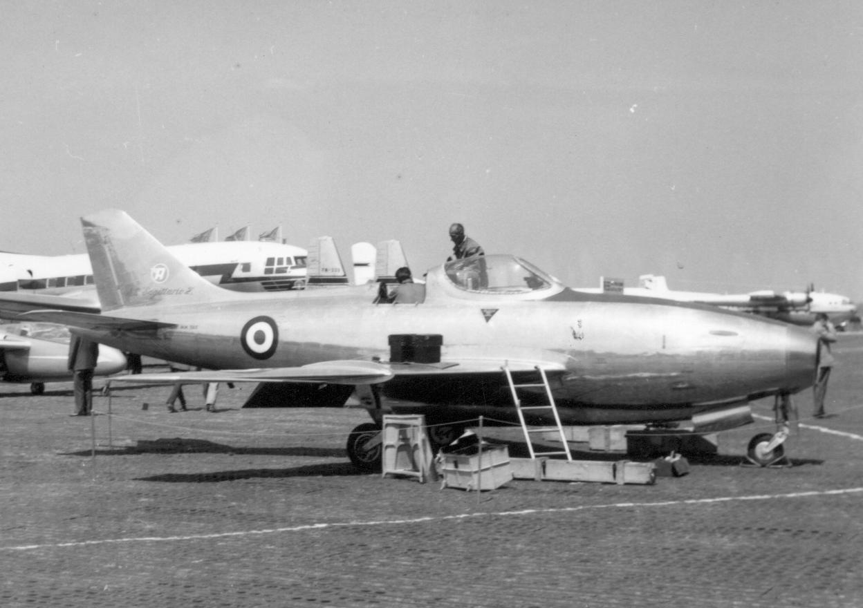
Vickers Supermarine Type 508 mock-up,

Vickers Supermarine Type 508

Vickers Supermarine Type 508 VX133 in flight

Britain broke its jet Bill Wyman with a bunch of pony planes. Look at this silly slag.

Northrop/McDonnell Douglas YF-23

https://upload.wikimedia.org/wikipedia/commons/b/b6/YF-23_front_right_view.jpg

Drive around Theydon Bois in a YF-23 and you’ll look like the fackin’ daddy. The Tarzan (Tarzan & Jane = plane) every bloody car wishes it was. The dog’s bollocks. Is it a Pelikan too? I dunno, don’t care.

Mysterious delta aircraft at Area 51: what is it?

Former British technical advisor Jim Smith considers what it may be

Speculative shapes based on Google satellite imagery discussed below

A recent article by Tyler Rogoway of the drive.com reported the possible discovery of a mysterious delta aircraft shape in satellite imagery of Area 51, the remote base in Nevada used by the US to flight test secret prototype aircraft, and to evaluate foreign materiel. The imagery is somewhat hard to interpret, as the aircraft outline is confused by shadows, and by what appears to be a framework erected over it – perhaps intended to support a pergola or tent-like structure intended to provide concealment.

The principal USAF programme which might generate a prototype of this general appearance is the Global Air Dominance program, which has appeared to be directed at producing a very low signature air superiority system. This programme, from the Drive article, is now identified as Next Generation Air Dominance, Global Air Dominance perhaps being too provocative a title.

I have previously written a little about the Global Air Dominance system (GAD) for @Hush_Kit at the following link, which examined future aerospace technologies:

This contained some speculation about the Global Air Dominance System:

“Our system-of-systems approach has, as one of its objectives, reducing the risk to human operators. It does this by essentially postulating three forms of vehicle – un-crewed, autonomous, survivable, and persistent platforms, like our intelligence, sensor and command and control platform; un-crewed, autonomous and ‘attritable’ platforms that the operators are prepared to lose if necessary when attacking strongly defended targets; and crewed, survivable platforms, used only where a human in-the-loop and on-the-spot is critical.

We can examine what is reported about current projects and programs and see this thinking in action. Alongside crewed aircraft concepts and programs such as the B-21, Global Air Dominance System and F-35, we can see the Unmanned Wingman, the XQ-58A Valkyrie un-crewed strike platform, Neuron, Taranis, as un-crewed and potentially ‘attritable’ platforms. We have the US Navy experimenting with autonomous air-to-air refuelling using the X-47B and no doubt un-crewed electronic warfare, jammer, and decoy projects already in hand. We have at least early attempts in high-flying, difficult to detect autonomous sensor and communication systems like the RQ-170 Sentinel and speculation about the RQ-180. Autonomous manoeuvring air combat is perhaps a little further away, although some might argue that Surface-to-Air Missiles and Cruise Missiles are simply ‘fully-attritable’ un-crewed autonomous air combat and strike systems.

The detailed roles and implementation of the US Global Air Dominance System (GADS) remains an area for speculation. This is expected to be a manned, stealthy platform, with long endurance, and is likely to feature sensors, command and control and battle management systems. Given the developments in autonomous adjuncts, it is possible that the weapons capability of the GADS may be limited, although there have been recent suggestions that it may employ directed energy weapons.”

More specific speculation about progress towards a demonstrator for this system is contained in:

This suggested that a near delta configuration was likely, with no, or minimal fins, to minimise signature while providing a platform with the ability to loiter in contested airspace; to deliver command and control capability, possibly over unmanned systems; and to deliver a variety of air-to-air and strike weapons.

Where does the newly-sighted aircraft at Area 51 fit in?

Clearly this is a question which cannot be answered accurately from outside the program, and could not be answered publicly by anyone inside the program. I will start with an assumption that the aircraft imaged was a demonstrator for part of the GAD system.

If this is the case, a number of interesting questions arise, the most obvious being what is being demonstrated? Here there are a range of possible answers, and, indeed a menu of options, somewhat depending on whether this is a technology, an operations, or a systems integration demonstrator.

A technology demonstrator could, for example, be examining novel control systems, and their impact on manoeuvrability, on signature, on stability and control, or on performance. An operations demonstrator could be used to examine the operational functionality of a mixed manned and unmanned system, or, perhaps, the robustness of an operating concept to cyber or electronic warfare threats. A systems integration demonstrator could be looking at how and where decision making should lie in a complex system, the communications, command and control and intelligence requirements, and so on.

The potential complexity of possible GAD systems is such that issues of this nature could be quite prevalent, and that early demonstration to gain confidence in the system architecture is likely to be essential.

There is a significant problem with this approach, and that is that validating the system architecture before demonstrating elements of the system has not been a strong point of the US, where it appears much easier to fund the demonstration of separate system elements, rather than the arguably more difficult task of making sure the demonstrated elements will work as a system.

From the outside, it seems far from clear just what the role of manned elements of the GAD system will be. Possible roles include a stealthy and networked air superiority capability; a similarly stealthy and networked persistent strike capability; or a command and control node authorising and controlling autonomous and semi-autonomous intelligence, communications, strike and air combat systems. It is also not clear whether the vehicle seen in the imagery is manned, remotely operated, or autonomous.

Configuration aspects

The air vehicle shown in the images has a double-delta planform, with highly swept inner wing leading edge, and a less swept outer wing, which may carry some upward canted fins at the wing tip. The drive.com article draws similarities between this planform and that of Concorde, which used a blended ogival platform.

Development of a multidisciplinary design optimization framework for an efficient  supersonic air vehicle | Semantic Scholar

The planform also resembles the ‘Arrow-wing’ double-delta planform examined by NASA in the US as part of American efforts to produce a supersonic civil transport aircraft. Unsurprisingly, there are also similarities with planforms examined by Northrop as part of an Efficient Supersonic Air Vehicle programme.

Aerodynamic Modeling Techniques for Efficient Supersonic Air Vehicle  Multidisciplinary Design Optimization

All of this suggests a strong interest in supersonic capabilities for a GAD aircraft, and if this is the case, a design Mach number of about 2.2 would appear sensible, both from a materials perspective and from the geometry of the design.

However, one might argue that the key characteristics required by the future manned element of a GAD system would be undetectability and persistence, and one might question how useful a supersonic capability would be in this context.

Multidisciplinary Analysis and Design Optimization of an Efficient  Supersonic Air Vehicle | Semantic Scholar

Again, this is difficult to address from outside the programme, and goes to the heart of whether the aircraft in the images is intended to be a stealthy platform with modest performance, whether it is intended primarily as a stealthy strike platform, or whether it is a stealthy, supersonic, fighter.

At this point, one must be open-minded. To attain Air Dominance, one needs to defeat defensive air threats, and deter or defeat offensive threats. It seems unlikely that this could be done with a subsonic aircraft relying on undetectability and capable AAM to achieve air superiority. But, to retain air superiority, persistence is required, and it seems unlikely that this can be achieved in the suggested Flanker-sized platform, unless significant numbers were available.

B-21 Raider - Northrop Grumman

Perhaps this is a supersonic demonstrator validating control systems for an extremely stealthy replacement for the F-22, or even the SR-71. Perhaps it’s a mini B-21, providing a (possibly autonomous) stealthy strike capability. Perhaps it is demonstrating a manned command and control system. At this point, it is difficult to do more than speculate.

I leave the last words to Queen:

Is this the real life?
Is this just fantasy?
Caught in a landslide,
No escape from reality
Open your eyes,
Look up to the skies and see …

Top ten sexiest rear-ends in aviation

North American Aviation XB-70 Valkyrie S/N 62-0001 – Military History of  the Upper Great Lakes

“I like big butts and I cannot lie. You other brothers can’t deny.” So said Sir Mix-a-Lot, in the popular song which earned him his knighthood. Whether it be the bootie, the bum-bum, the backside, the keister or the posterior, the tail has inspired the imagination of humans since buttocks first evolved 2 million years ago as a form of mobile biological scatter cushion. Jump to the 20th century and the Wright Brothers’ aeroplane leaps into existence rear-end first, and so begins the story of the flying tooshie. Sam Wise, assman and aviation aficionado went in search of the 10 sexiest rear-ends in aviation.

Douglas F4D Skyray

The F4D scores extremely high in the Batmobile Index of aeronautical beauty

The Douglas Skyray is the best-looking American fighter aircraft ever made. It was an especially elegant aeroplane, from the early jet era when an aeroplane could look like a flying manta ray rather than today’s unlovely priests of the church of angle alignment.

The swoop of those leading edges belie the aircraft’s speed, and in fact Douglas’ last fighter once held the world absolute speed record, moving to the jet’s rear-end they continue to intrigue the eye, drawing back into that single jet exhaust pipe that never fails to delight. But what really excites the mind are those suddenly, surprisingly pointed pitch-trimmers just outboard of the fin, a jagged steel among the beautiful curves.

Dornier Do 335

File:Dornier Do 335 at NAS Norfolk in 1949.jpg - Wikimedia Commons

You’ve heard of propellers on the front of a plane…but propellers at the back and the front? As utterly mad as that sounds, it has in fact been done before, on the German Reich’s seemingly daft, yet formidable, Do 335. The Pfeil, designed to outpace existing twin-engine designs hence the unconventional engine and airscrew layout, couldn’t work as a taildragger like most aeroplanes of the time but instead features both a dorsal and ventral fin, like some sort of propeller-driven missile (or, I don’t know, a submarine or something. Either way, it looks rad).

Lioré et Olivier LeO 45

Lioré et Olivier, LeO 451.jpg

Anyone who has ever seen any pre-war French bomber will probably be surprised to see one appear on a list of anything sexy, and from the front the LeO 45 is anything but, perhaps most kindly described as “definitely resembling a plane”. Mais á la derriere, ooh la la, regardez ça! Twin tails are always cool, but the horizontal dihedral with the dropped vertical stabilisers look positively futuristic, maybe even kind of predatory. Completely different to everything in front of it, anyway.

Mikoyan-Gurevich MiG-25 Foxbat

This Russian Super-Jet Could Fly So Fast It Blew Up Its Own Engines | The  National Interest

In contrast to the above, the famously fast MiG-25 ‘Foxbat’ has an absolutely Pixar-mum-level dumptruck ass. That thing is thicc – Sir Mix-A-Lot wrote a Billboard Hot 100 number 1 hip-hop single about this fighter. There aren’t many jetpipes that occupy the entire, full area of the fuselage but these ones, from behind…I mean, look at it!

Everything You Need To Know about the Mig-25 Foxbat
Bigger and more pleasant than the average £2000 per calendar month London flat, the jetpipes of the MiG-25.

And that’s before the afterburner even comes on, and then we’re talking about one of the greatest lightshows on the planet Earth as two burning suns push this monster to Mach 3 (ish), melting brains the whole way. Two lovely small ventral fins even give a delicate garnish to the main dish.

The extraordinarily beautiful Hush-Kit Book of Volume 2 will begin when funding reaches 100%. To support it simply pre-order your copy here. Save the Hush-Kit blog. Our site is absolutely free and we want to keep it that way. If you’ve enjoyed an article you can donate here. Your donations keep this going. Treat yourself to something from our shop here. Thank you. 

Aerfer Sagittario 2

Italian madness | Aerfer Sagittario 2 | War Thunder Air gameplay | - YouTube

Yeah that’s right, I know obscure planes. This could be seen as a ‘Ferrari Yak-23‘, and possessed the most beautiful, proportionally balanced empennages I’ve ever seen (I believe me I’ve seen some). The absolutely graceful lines as the tail tapering from the bulging fuselage just make me melt. In side profile the way the thing curves upwards gives the impression that the aircraft is about to spring into the air like an antelope and up close you just want to run your hands over every rivet as it sweeps and bends like a work of art, untroubled and undisturbed by any engine exhausts or nozzles.

Ambrosini (Aerfer) Sagittario 2 MM560 LeB 29.05.57.jpg

Savoia-Marchetti S.66

Savoia-Marchetti S.66 - Wikipedia

The considerably more bonkers S.66 may be best known for that utterly bananas body, but shift your gaze and you’ll find the back-end is doing something very interesting indeed. Check out how slender those booms are – nothing but frame, pure function over form, leading to a tailplane that looks almost like it’s floating in its own right as a result.

Pin on F-boat

The fins appropriately resemble tall-ship sails, suitable for the time when people thought commercial aviation was going to be a primarily water-based affair, while the tailplane itself very much commands respect as its own entity, working in fantastic opposition to the huge wing it follows.

de Havilland Sea Vixen

Sea Vixens and Phantoms Catchin' The Trap On WWII Era Carrier - World War  Wings

Another twin-boom design, the Sea Vixen makes the list for having a tail like a great big fuck-off spoiler. There’s really not much more to say about it I’m afraid, it just looks like a sick, fat spoiler like on a racing car, and that’s very cool.

If you hurry with your pre-order you can still get your name included in The Hush-Kit Book of Warplanes here

McDonnell Douglas F-4 Phantom

A British F-4K Phantom II from 892 Naval Air Squadron is launched from the  U.S. Navy aircraft carrier USS Independence (CV-62) during the NATO  excercise "Ocean Safari", in November 1975. [1525x1141] :

The Phantom’s rear-end is easily one of the most iconic rear-ends in aviation history. Aside from the two big cans of fire, it’s the way the tail extends out above them, the fillet between the nozzles separating them and housing the arrestor hook, the short, high-angle fin, but most of all it’s those downward canted elevators. The whole combination is instantly recognisable, one of the defining features of one of flight’s biggest rockstar icons. The Phantom’s tail is the powerful, musclebound hindquarters of a true beast of the sky.

Vought F7U Cutlass

Vought F7U Cutlass: America's 'Nazi' Fighter Jet? - 19FortyFive

The polar opposite of the extremely successful F-4 is the calamitous Cutlass, the F7U Cutlass is probably the biggest meme plane to ever be built. A very real contender for “worst plane in history”, this jet’s Wikipedia page reads like a dark comedy and it’s the only naval aircraft ever to be straight up wholesale ordered off an aircraft carrier by its captain. As he watched them go, he would have nevertheless greatly admired the fantastic design of the back half of the plane. The engine housing sticks out past the wing in a fantastically 1950s manner while the awesomely-shaped tails just go directly out the back sans booms. Gerry Anderson must have loved this design, but not even International Rescue could have saved this plane from being a disaster.

Blue Angels demo the notorious Vought F7U Cutlass (aka "Gutless Cutlass")  circa 1953. They hated it, just like everyone else. : r/aviation
Vought F7U-3M "Cutlass" (BuNo 129704) with "Sparrow I" mis… | Flickr

Saab 37 Viggen

Saab S37 Viggen | Plane-Encyclopedia

The Viggen, you ask? But Sam, how can you end this article on such a conventional-looking aircraft after such extremely correct examples above? Surely this is a mistake? And yes, you’re right, at first glance, the Viggen is just a boggo delta wing layout (I mean, it’s not, it’s one of the best-looking planes ever but you know) with nothing remarkable going on outback.

Saab 37 Viggen Fighter

.

But then the wheels hit the floor and the clamshell doors close and, oh boy, something funny goes on below the belt. Woof. The Viggen’s party-piece is its powerful thrust-reverser that can bring it to a stop on a krona, and can even be used to reverse with. It looks so, so good when those things slam shut.

Sam Wise has a lot of opinions, many not his own. You can read them on Twitter.

This jet was the one of Navy's deadliest fighters — for its pilots - We Are  The Mighty

Model bitch-fight! Tempest fury at Checkmate attention

Storm Warning Comes from UK in Form of Project Tempest | Defense News:  Aviation International News

Today a plastic model made to promote Britain’s ambitions to produce a future combat aircraft sparked controversy when it publicly attacked the Russian Sukhoi Su-75 Checkmate model.

Speaking from a low-security shed in Warton, the model held a press conference this morning. The Tempest started by saying, “I am just as real as that Russian, yet nobody treated me like a real plane. This is really hurtful especially considering MiG’s bullshit history over the last twenty years. They tried to sell second-hand MiG-29s as new by painting them nice and have spent like a gazillion years to get MiG-35s into service and it costs about the same as the far better Su-35, yet…” At this point journalist Stephen Dave Dave Steven Stephens from the Passive Defense Aerospatial Awareness Journal heckled the Tempest model, shouting, “The Checkmate ain’t a MiG!” Without acknowledging her mistake, the Tempest model changed tack, noting that, “Sukhoi has taken like a gazillion years to get a handful of Su-57s into service – and they don’t even have the real engine yet do they?”

The Checkmate model responded later in the day (from a Moscow mixed recycling bin) opining that “The Tempest model is a joke, I’m full of real bits and I’m from a legitimate superpower. The wheel fell off the UK’s penny-farthing years ago yet they continue banging on with fantasies of greatness. Their last real fighter aircraft took its first flight in 1957! So as far as I’m concerned they can eat a bag of blini pancakes.”

The European Fuck-Ass mock-up was unavailable for comment.

Top 10 Things that made the P-51 Mustang fighter aircraft so outstanding

Aerospace Engineer Joe Wilding examines why the Mustang was so good.

I want to start with an embarrassing confession. With a lifelong obsession with aircraft and a few decades of experience engineering them, you might think I’d have an insightful and obscure favourite airplane (or ‘aeroplane’ as Hush-Kit would have me say). But the answer will disappoint you. Like many, I absolutely love the P-51 Mustang. I have tried hard to come up with a more sophisticated answer.

Joe Wilding (@joe_wilding) / Twitter
Joe Wilding

Despite some strong contenders, I keep coming back to the Mustang. The Mustang is the Jimmy Stewart of airplanes. Both are solid performers with dashing good looks, and few have a negative comment for either one. The Mustang’s graceful curves draw you in. The performance and technical details are what keep me coming back. It’s the best of both worlds: a stunning piece of art and a technical marvel. While the art claim is uncontestable, let’s dive a little deeper into the technical claim.

10. The Wing is the Thing

Almost any discussion about the Mustang starts with its wing. But the real advantage of this wing might be different from what you’ve heard. Because of its mid-war development timing, the Mustang was the first aircraft to implement a new aerodynamic theory called “laminar flow”. This effect, contrasted to turbulent flow, is an elusive condition that is possible with the right wing shaping and attention to detail. All wings have a small amount of laminar flow at their leading edges. A laminar flow design extends this region to a majority of the wing surface and can reduce the wing drag by an incredible 25%-50%. Unfortunately, the practical application usually falls short of the theoretical promise. Manufacturing flaws, battle damage, hangar rash, and bug guts alter the surface of a wing, and the laminar flow benefits fade away when the shape is not pristine. 

The extraordinary beautiful Hush-Kit Book of Volume 2 will begin when funding reaches 100%. To support it simply pre-order your copy here. Save the Hush-Kit blog. Our site is absolutely free and we want to keep it that way. If you’ve enjoyed an article you can donate here. Your donations keep this going. Treat yourself to something from our shop here. Thank you. 

However, the Mustang wing has another aerodynamic trick up its sleeve. By complete serendipity, the shaping of a laminar flow airfoil is also very good for low drag at high speeds due to Mach effects. The airflow over a wing accelerates even faster than the airspeed of the aircraft. At high enough aircraft speed, this local wing airflow will exceed the speed of sound. When this happens, drag increases to really high levels, really fast. To keep accelerating you need a lot more engine power. The shaping of the Mustang wing lessened this airflow acceleration and allowed it to fly a little faster before this drag started its dramatic rise. In modern terminology, the Mustang had a great transonic wing. This effect was not fully understood in the early 1940s, but the science quickly followed up. Nearly all jet aircraft that followed (and a few piston-engined fighters) capitalized on this idea.

A final note about wing design relates to its size. Going fast and far generally favors a small wing. Maneuvering and turning hard favors a larger wing. If you look at the wing loading (aircraft weight divided by its wing area) of various contemporary fighters, you’ll find that the Mustang was in the middle of the pack. This was the perfect choice given its balanced mission of dog fighting performance, at long range.

9. Very Low Drag

In addition to the great wing design, the Mustang also had a remarkably low overall drag. The performance of the airplane is the summation of many little things and a close attention to detail. A close inspection of the Mustang will show its remarkable cleanliness. There are virtually no bumps, bulges, or inlet scoops anywhere on the plane. Most other planes of the era have a multitude of these to address various cooling or system details.  The landing gear is a great example. The main gear is fully enclosed by gear doors that fit well. The tailwheel is also retractable, unlike most aircraft of this era. 

The North American P-51 Mustang: A “Little Friend” with a Big Impact | The  National WWII Museum | New Orleans

Cooling drag is another area of excellence for the Mustang. Many sources will talk about the belly radiator system producing thrust by adding heat energy to the airflow. The test data shows that very little positive thrust is ever produced. However, in most high-speed conditions, the system is producing no net drag (i.e. the thrust produced is offsetting the drag of the scoop and the airflow through the radiator). This effect is important, as cooling drag at high power can be quite large. Several clever details contribute to this high-efficiency cooling system. First, the cooling duct contains the combined heat exchangers for the engine cooling, the aftercooler, and the oil cooler. This maximizes the energy transfer with minimal impact to the aircraft. Secondly, the installation of the cooling system is nearly perfect. The inlet is below the wing, maximizing the inlet air pressure. It is also offset from the wing surface which bypasses the low energy boundary layer airflow, which would decrease efficiency. The aft fuselage allowed for a large radiator, which reduces internal flow losses.  The airflow exit is behind the wing where the fuselage starts to taper back, placing it in a region of low local air pressure. Finally, the system has variable outlet doors, controlled by an automated system in all phases of flight. Together all these details promote ideal flow through the system and maximize efficiency.

One last detail which results in low drag / increased thrust is optimal shaping of the engine exhaust stacks such that the exhaust airflow produces net positive thrust. Test data shows that at high-speed cruise, this effect increases the net thrust by 20% or more.

Low drag is not just about going fast. At any speed, lower drag means lower engine power, and lower fuel burn. This translates into an increase in aircraft range, which we will talk about next.

8. It Goes the Distance

US P-51D Mustang accompanies the B-17 bomber

Most fighters before the Mustang were not designed for significant range. Early in the war, fighters were used mostly as bomber interceptors and the air battles would take place near the fighter’s home airfield. The exception to this was fighters that were used in a ground attack role or for other missions such as photo-reconnaissance. This was the initial design mission for the Mustang, and hence the aircraft was designed for greater range.  As the Mustang was entering service in 1943, the US Army Air Corps was executing a daylight bombing strategy and was starting to suffer heavy bomber losses to enemy fighters. It began using the Mustang for long-range bomber escort. The Mustang’s low drag meant it could cruise with lower fuel burn than other contemporary fighters, and thus fly even further on the same fuel. Range was further increased with an additional fuselage tank and wing drop tanks All of this gave the Mustang sufficient range to escort bombers round trip anywhere in Germany and even into Eastern Europe. Several other long-range fighters like the P-38 and P-47 approached this capability. Although the Mustang has less maneuverability compared to some of the lighter fighters, like the Spitfire and Bf 109, it was superior to the P-38 and P-47 which were larger and heavier. The Mustang had the right balance.

7. Amazing Development Story

The Mustang has a great origin story. Prior to World War Two, North American Aviation had developed a family of successful training aircraft. They desperately wanted to get into the lucrative fighter business, so they started building a team to accomplish that. At the outbreak of the war, they had the early concepts for a fighter that incorporated much of the latest thinking in fighter optimization, including the radical new wing concept. In early 1940, with the war starting to heat up, the British urgently wanted more fighter aircraft, and asked North American to build P-40’s under license. North American, seeing this as the chance to finish their original fighter design and have an immediate customer, essentially told the British, “Hold my beer.” The British took a gamble on the offer, and magic ensued. There are three common ingredients for a successful rapid aircraft development program: a team with the right expertise, the necessary funding and tools, and a challenging but realistic deadline. The North American team had all three and it was off to the races! Based on the team’s prior research and design work, they rolled out the prototype aircraft in an unprecedented three and a half months, and it flew a few months later. To be clear, the design wasn’t perfect, including an early crash of the prototype. But it was very good. The team was able to work out the bugs and was delivering the initial aircraft to the British in October 1941, roughly 18 months after the contract was signed.

File:120th Fighter Squadron - F-51 Mustangs.jpg
  • 6. The Merlin!
June Allyson - Movies & Autographed Portraits Through The Decades

If the Mustang is Jimmy Stewart, then the Merlin engine is June Allyson. A match made in heaven! (And yes, I get the irony in that analogy.) It is an engine that is loved by everyone, and for good reason. Don’t worry Allison fans (the engine, not the actress), you’ll get your due credit shortly. As the Mustang entered service, everyone was impressed with its solid performance, particularly at low altitudes. However, the original Allison engine had a single-speed, single-stage supercharger, and its power output dropped off quickly above 15,000 feet. The most recently upgraded Merlin engine had a two-speed, two-stage supercharger that could shift gears and continue producing high levels of power through much higher altitudes. Both the British and Americans started speculating on what the aircraft could do with the Merlin engine, and teams in both countries started projects to retrofit a Mustang with the engine. The British were slightly ahead, and their prototype flew a month before the Americans in October of 1942. Both teams quickly realized it was the right combination, with high-altitude performance that exceeded any other fighter of the day. A vast majority of the Mustangs built used the Merlin engine, and its amazing success as a high-altitude bomber escort is because of this engine pairing.

  • 5. The Allison!
P-51 Mustang | Facts, Specifications, & History | Britannica

I don’t know the best comparison for the Allison engine, but maybe Cinderella? It certainly gets overshadowed by its boosted step-sister, the Merlin. The base engines are remarkably similar, with the later Merlin supercharger being the primary difference. And the Merlin did have a truly world-class supercharger design that the Allison lacked. However, the benefits of the Merlin supercharger are best at higher altitudes. For any missions where low altitude was required, the Allison was a worthy contender. In fact, at lower altitudes, the Allison was slightly superior, due to the pressure mapping of the supercharger. For missions like ground attack (the original role for the early Mustangs), the Allison was a nearly perfect engine and the aircraft operated exceedingly well in that role. This is reflected in low-altitude speed and climb rate data. Although, these comparisons are hard because some later Merlin-powered Mustangs with higher boost could beat the Allison at all altitudes. 

The Allison probably doesn’t get proper credit because the P-47 entered service soon after the Mustang and, with more armament, it was an even better ground attack aircraft. (The-P-47 was also an effective high-altitude aircraft with its unique engine / turbocharger installation.) Due to the urgent need for long-range, high-altitude fighters, most Mustang production transitioned over to the Merlin-powered model which quickly eclipsed the Allison-powered Mustang. And that is a shame. I am a fan of both aircraft, for different reasons, and I wish the Allison got a little more love. 

  • 4. Bubble canopy

The Mustang was one of the first aircraft to sport a fully unobstructed bubble canopy. This innovation came to reality mid-war as polymer plastic material science matured. One of the first iterations of this technology pioneered on the Spitfire, was called the “Malcolm hood.” This was a hybrid solution that replaced the centre canopy section with a slight bubble Perspex canopy that contained no obstructions. This gave better visibility both laterally and vertically. But since the basic airframe was not modified, the aft view still suffered. This Malcolm canopy was retrofitted to B and C model Mustangs soon after the Spitfire. Both aircraft were going through a rapid evolutionary cycle and the next version of each aircraft (the Spitfire Mk VIII and the P-51D) took this idea a step further. In both cases, the canopy was enlarged, and the aft fuselage lowered to give an unobstructed view in nearly all directions. This idea did increase aircraft drag slightly. (Test data shows an increase of roughly 2%.) But that is a small trade for better pilot situational awareness. This canopy design became the norm for nearly all fighter aircraft that came afterwards and remains the standard today. The clean bubble canopy strongly contributed the P-51D’s “modern” look as compared to the razorback fuselage and glazed canopy design of previous fighters.

Miles M.20; The Aircraft Equivalent of the STEN Gun - - Military Matters
A bubble canopy is a canopy made with minimum or no bracing, to provide the pilot with an unobstructed view. The majority of a bubble hood is one piece. Though some experimental bubble hoods were tried in the First World War, and some later ones came close (including the Me 209) the first truly effective modern one was a feature of the Miles M.20 fighter (1940) pictured here, a type that failed to enter service. Later in the war many types including Fw 190, Tempests, P-38s and some P-51s had bubble hoods.
  • 3. Designed for Mass Production
North American P-51 Mustang | Page 6 | Aircraft of World War II -  WW2Aircraft.net Forums

Often engineering marvels are the equivalent of a Swiss watch. They might exhibit extreme performance, but they give up practicality in the process. They are either prohibitively expensive, difficult to maintain, or they compromise useability to maximize their primary performance metric. An example of this type of design philosophy would be a racing vehicle. They are typically hand-built in low volumes, expected to last for just a few races, and are expertly maintained, often by their creators. The Mustang is the opposite of this. It was designed for profitable mass production and operational effectiveness from the beginning. An example of this philosophy is the wing and the tail. Despite the Mustang arguably having the best performing wing of the war, it was also amongst the simplest. It had a trapezoidal planform with straight leading and trailing edges. This not only is simple and cost-effective to build, but it contributes to the higher manufacturing accuracy needed to achieve its aerodynamic efficiency. Straight lines are easier to align when building tooling, especially in the 1940s without the use of modern laser projection and measurement tools.

Is it possible to quantify this design emphasis for production? Comparing aircraft production costs is challenging, especially between different countries. Labor hours per aircraft is more comparable, but the data is mostly anecdotal. Production efficiency also evolved drastically during the war, with hours per plane in 1945 being much lower than in 1940. All of that considered, most data shows the Mustang as having one of the lowest hours to build, in some cases by as much as half when compared to comparable fighters.

2. Landing gear

There were several arrangements for main landing gear on fighters of this era. Most were conventional taildraggers, with a few tricycle exceptions like the P-38 and P-39. The primary design difference between the taildragger aircraft is the direction of gear retraction: inward, outward, or aft.  Each layout has pros and cons. 

Landing gear generates high loads and outward retracting gear connects to the wing inboard, where it is stronger. This offers weight savings and was used on the Spitfire and Me-109. This layout also has a compromise: it tends to make the gear width somewhat narrow, which can lead to stability issues when landing. The mustang had inward retracting gear which allows for a wider gear stance. If a pilot lands with a wing low, a wider stance gear has a better ability to correct the roll angle on touchdown, without over-turning. Additionally, a wider stance gear allows for higher turning forces on the ground before the aircraft pivots on the outer gear and drags a wingtip. Spitfire pilots tended to cope well with its gear arrangement, probably due to superior training. However, more than 10% of all Me-109s were lost in landing and takeoff accidents. This landing gear likely has a strong influence on this statistic. 

A final advantage of inward retracting gear is it places the retracted wheel in the center portion of the wing where it is thickest. This allows the wheel to be fully enclosed within the wing surface with no drag-producing bumps or blisters. Many contemporary fighters contained these (or exposed wheels), including the Spitfire and the Me-109.

  1. Conical Lofting

This might be the most obscure detail that contributes to the Mustang’s greatness. As an aircraft designer though, it is one of my favourites. The Mustang was one of the first aircraft to use a geometric design process referred to as “Conic Lofting.” Before we get into why this matters, let’s start with some definitions. “Lofting” is the process of creating the external shape of the aircraft, and the “Loft” refers to this final shape. The term loft comes from the shipbuilding industry where the shapes of ship hulls were drafted (often at full scale) in a loft above the shipyard. Early aircraft development borrowed much from shipbuilding, including this term. In more modern language, the loft represents the collection of external aircraft surfaces. 

“Conic” refers to a type of mathematically defined curve. A conic curve is generated by slicing a plane through a cone, hence the name. A circle and an ellipse are both conic curves, among others. The advantage of a conic curve is that it can be described with high mathematical precision, and it is guaranteed to be a smooth curve with no reversal of curvature (assuming it is built per the definition). This type of lofting provides two related advantages. First, it tends to produce aircraft surfaces that are very smooth and continuous, and thus promotes low drag. Secondly, these surfaces tend to look really pleasing to the eye. If you look at a Mustang fuselage closely, you can see evidence of this. The forward cowling is an exceptionally well-designed shape in both cross section and the way the shapes flow from spinner to canopy. The aft fuselage between the canopy and tail is similar. 

Conic lofting is a minor detail on a practical level, but it is one more feature that puts the Mustang on a different level. As a footnote, modern lofts are generated by computer aided design (CAD) programs and conic lofting is one of several techniques still implemented today.

Bonus: It Just Looks Freakin’ Amazing.

There are exceptions to the endlessly repeated adage noting the correlation between good looks and good handling qualities. For instance, the American century series fighters were stunning, yet most had questionable handling characteristics. In the other direction, some would say that two aircraft named ‘Thunderbolt’ have questionable looks, yet no one would question their incredible effectiveness as combat aircraft. Few would argue that the Mustang is questionable in either its style or its performance. 

In summary, the Mustang stood out in its performance, its practicality, and its design. It was the right airplane at the right time. The incorporation of the best ideas from several decades of fighter evolution allowed it to become the pinnacle of piston-engine fighter design. Very few of its individual features are exceptional by themselves. But the Mustang brings them together in a very balanced and effective way. And it doesn’t hurt that the designers had an eye for good aesthetic design as well. This formula describes most of the greatest aircraft ever built.

Joe Wilding was the co-founder of Boom Supersonic, an independent company attempting to build a supersonic transport aircraft.

References:

Mustang, The Story of the P-51 Fighter, by Robert Gruenhagen

Mustang, the Untold Story, by Matthew Willis

Aircraft Design, a Conceptual Approach, by Daniel Raymer

The Secret Horsepower Race, by Calum Douglas

A History of Aerodynamics, by John D. Anderson

Various performance papers from the 1940s authored by North American Aviation and N.A.C.A